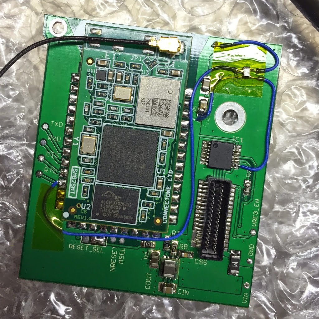
I’m going to call this one a success.
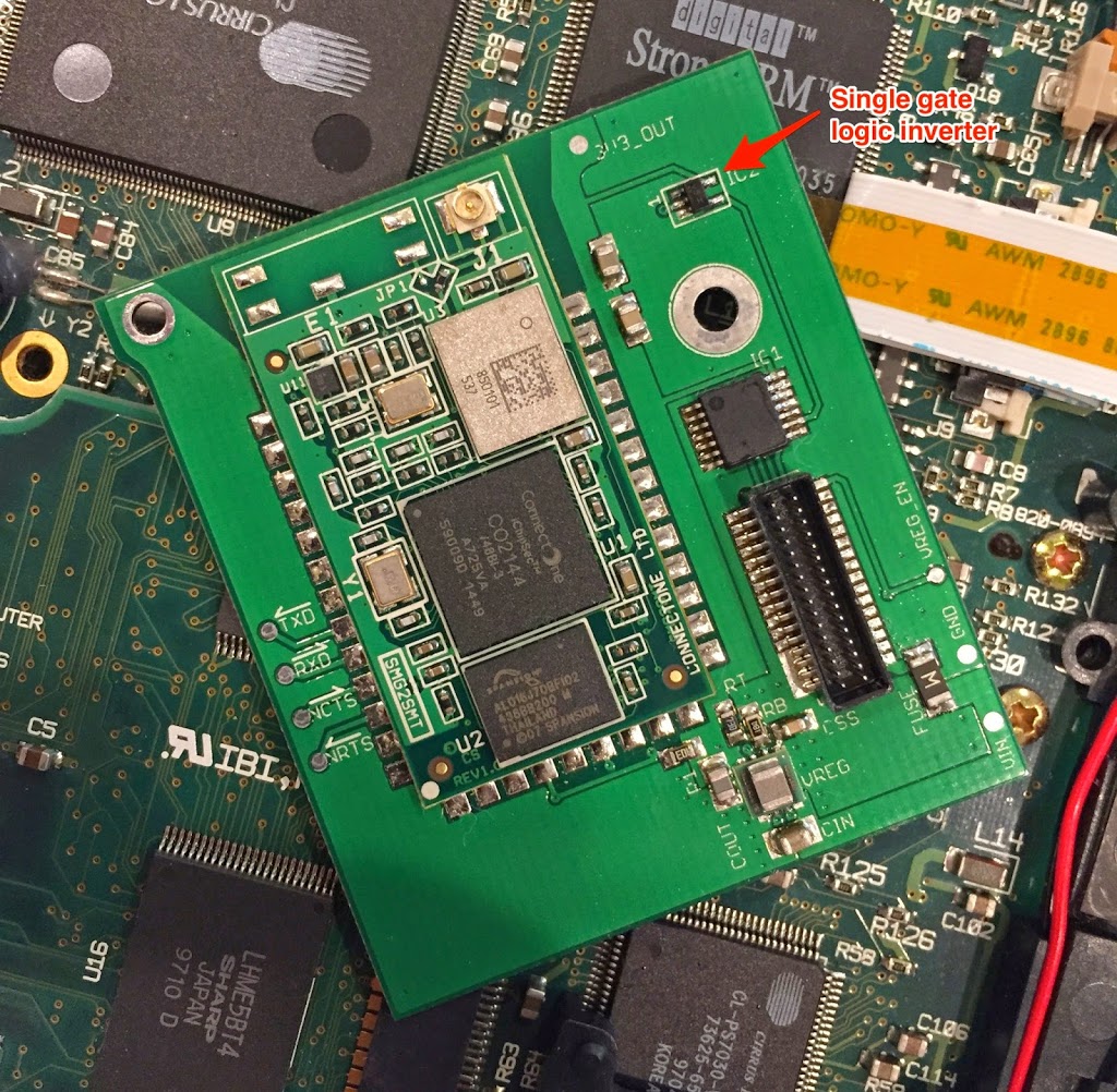
There is an error in the hardware flow control circuit, but that’s due to an error in the N2 Platform documentation. I’ll take responsibility because I should have more thoroughly prototyped (which I thought I had, but oh well) I’m still planning on hacking an inverter onto the board to fix the issue.
Even so. I’m chalking this one up as a success.
A few last details:
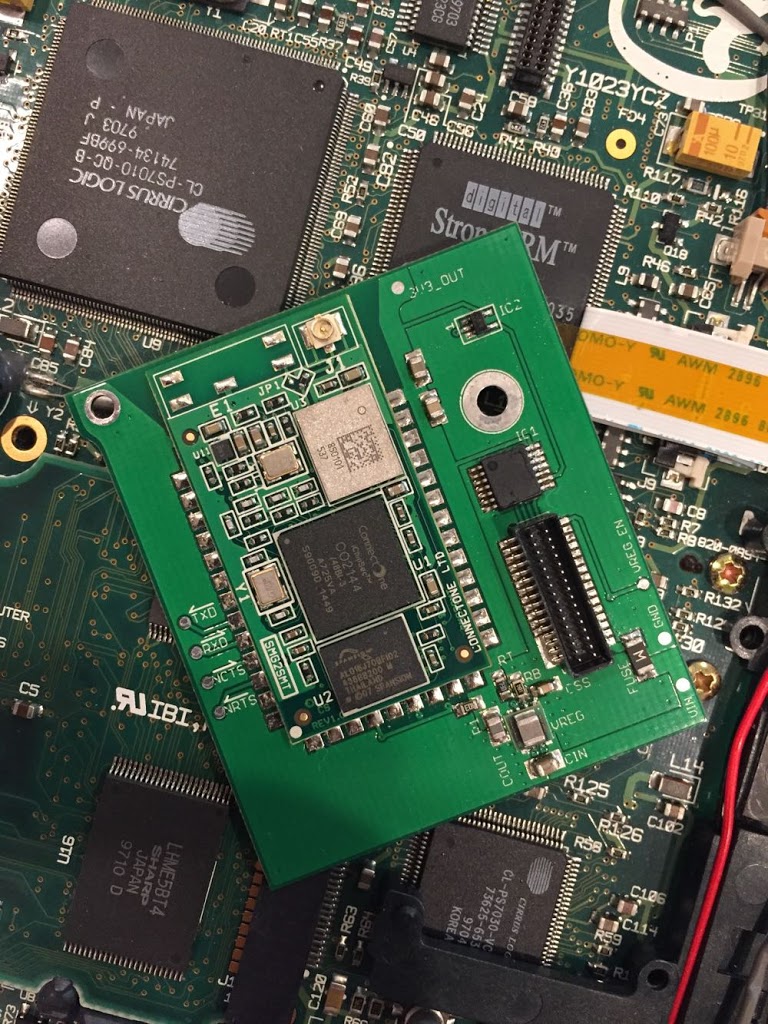
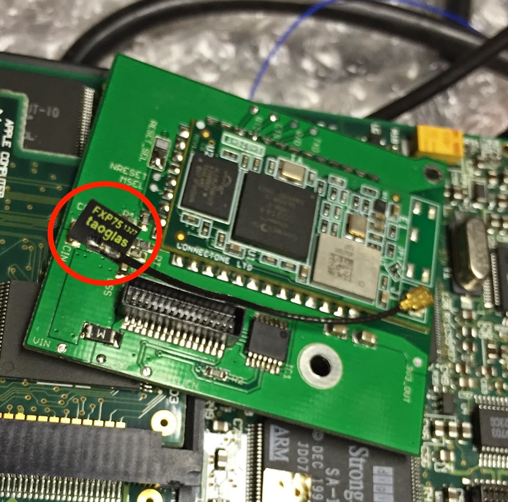
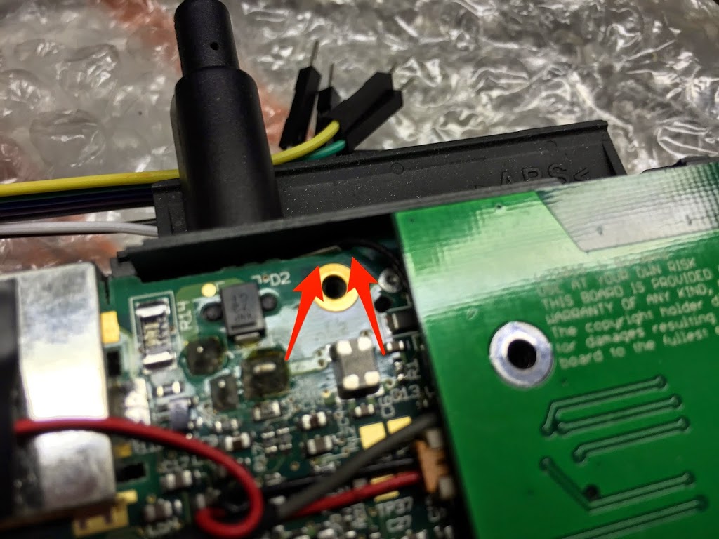
The Antenna
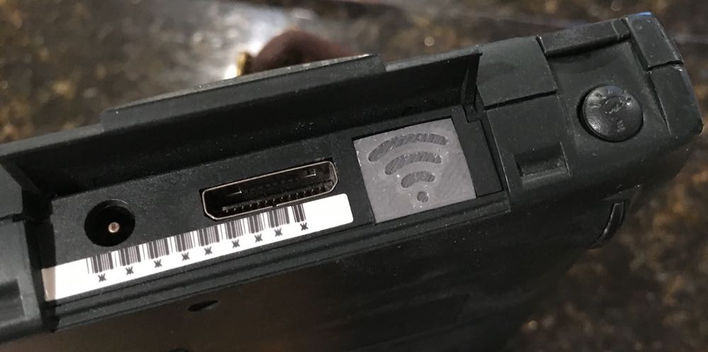
I found a really small antenna. I think its really for bluetooth devices, but it seems to work fine. It is so small, I was able to tuck it in a small gap between the power connector and the interconnect port.
WiReach Configuration
You need to send a few specific commands to configure the WiReach module. The most important is AT+iWANS=1 which tells the WiReach that the WiFi network is the WAN subnet. Also you need to configure a username and password (which matches the PPP configuration on the Newton.) AT+iRAU and AT+RAP are the commands you use to set the username and password. And of course you’ll need to connect to your network using:
AT+iWLSI=My_WiFi
AT+iWST0=4
AT+iWPP0=<WPA2 passphrase>
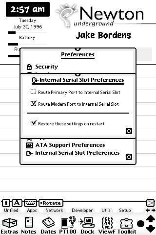
I use PT-100 to configure the module. Then a Serial Internet configuration with a script. The script is simple. First, it pauses for a few seconds to give the module time to power on. Second, it sends the at+iSPPP:0 command to start the PPP server. Finally, it waits for the OK.
How Does it Work?
My goals when I started this were:
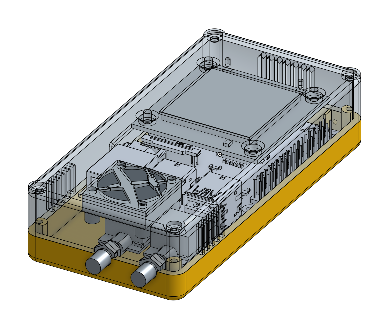
- The case had to close and everything had to be fully internal.
- Find an antenna and antenna placement that would work without modifying the case or the shielding.
- Enough range to reach my router from my couch…
- Connecting my Newton to a WPA2 network.
In all, despite the flow control thing, I’m pretty happy with the end result. The project meets my requirements.
I’m trying to decide if I want to do a v1.1 board with corrected flow control signals.