3D Printed Port Cover

Since the MP2x00 did not come with an internal modem (and one was never sold), each MessagePad came installed with a little plastic cover that fills the space where the RJ-11 jack would be.

This is the same cover where apple would place a “2100” sticker indicating that a MP2000 was upgraded to a 2100.
Due to an oversight, the WiFi card extended into the area where this plastic cover would sit.  (I’m not sure this could have been avoided, even if I had planned ahead)
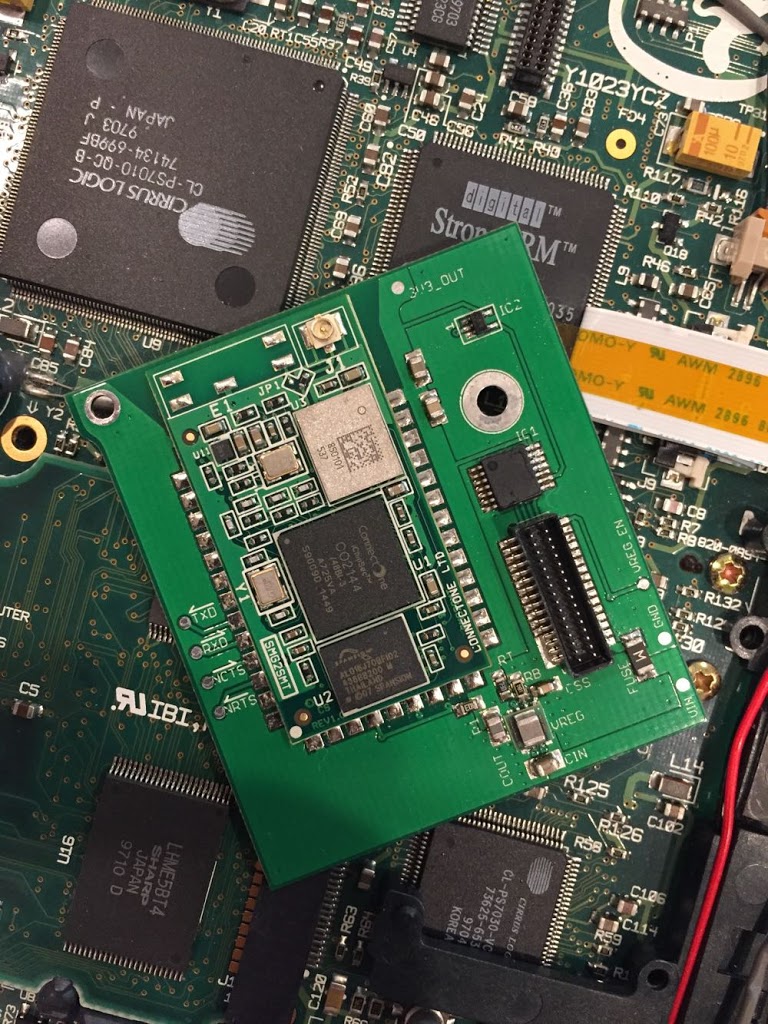
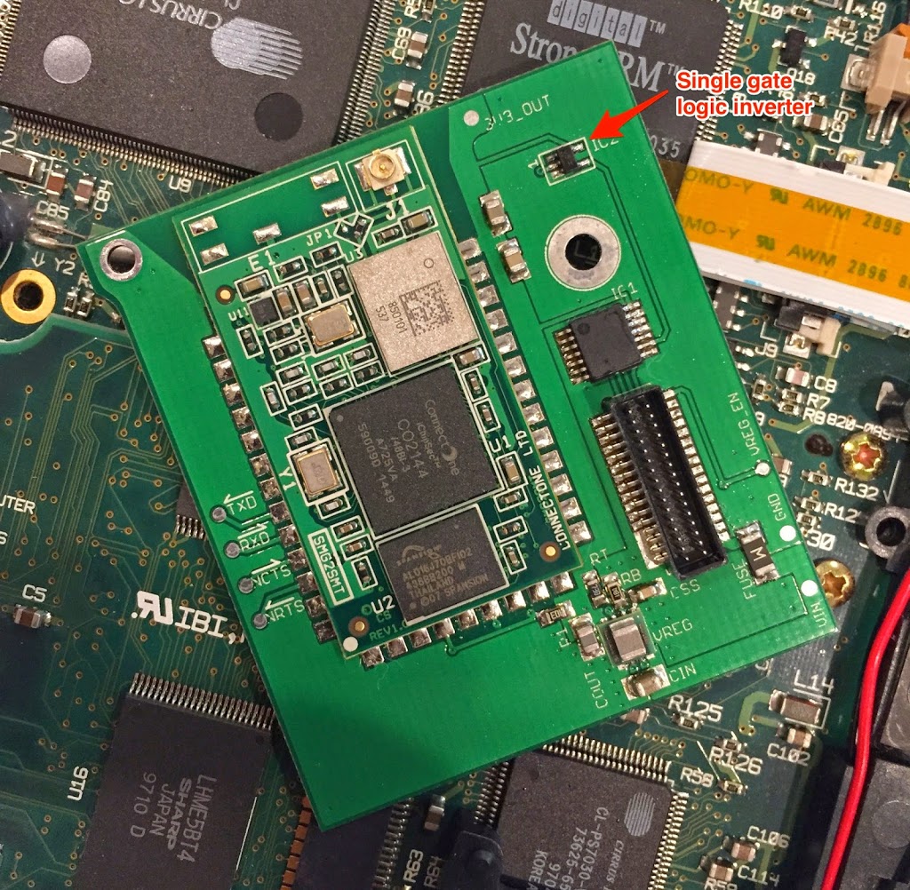
Instead, I’ve designed a replacement cover that does not interfere.  For good measure, I added an embossed WiFi logo to indicate that the internal WiFi card is present.

I think it makes for a nice finished product.

The STL files for the port cover can be found here: https://github.com/jake-b/Newton-Internal-WiFi/tree/master/Port%20Cover

WiFi Board v1.1

I got the revised boards and finally found some time to assemble a board.  This board adds a logic inverter to fix the flow control, and removes some extra traces for an alternate reset circuit.

To assemble the board, I had a stencil made and used it to apply solder paste.  Then I placed the components using a very simple “pick and place” rig:

This jig was made from a piece of brass tube, a leur lock fitting, some tubing, and a 22ga blunt dispensing needle.   It was mounted in a cheap USB microscope holder (available on eBay or Amazon) and hooked to a vacuum pump that I already had.   There are many more complicated versions of this rig on the internet, but this simple setup worked fine for me.

Finally, I baked it in a toaster oven that I got for free at a garage sale, and a rocket scream reflow shield.

Everything works great.  I consider this project a success.  All thats left to do now is to 3D print a replacement for the plastic “plug” that covers the hole in the case.

Finally, a little application that uses the method mentioned in an earlier post to enable the board when the ‘modem’ port is opened:

Thermal Performance and Loose Ends

Thermal

Early designs used a linear regulator to supply 3.3v from the Newton’s battery voltage.  It became pretty obvious that a linear regulator would get too hot, and so I changed it for a switching regulator.

I wanted to do a real world test.  The WiReach specs say that it can draw around 350mA peak during transmit.  I modified the Thumb sample code into a program that would output a continuous stream of ~25kB packets.  I taped a thermocouple to the regulator and ran the test for an hour or so.

The results were promising.  From room temperature, the regulator went from 77.4F to a high of 85.1F.  This satisfies me that in my normal use the board will not overheat.

A wise man once told me:

“People might be using such a Newton on a camp site close to Death Valley in August. Before you release such a circuit into the wild, you should put the assembly into the baking oven at 60 degrees centigrade and see what happens…”

Good advise, but I don’t think I’ll be performing that test.  I just can’t imagine putting a Newton in a oven for any amount of time.

This test is anecdotal at best, I guess.  Was the WiReach module anywhere near its peak transmit power or current draw?  I don’t know.  At 115200bps, I’m not sure that the Newton can saturate the WiFi module such that it would need to draw its maximum.

Physical

I found one other minor issue with the physical design.  I intentionally pushed the module as close to the edge of the Newton as possible– into the space where a telephone jack would have been for an internal modem.  The module is large and getting it in just the right place and keeping the board within a 5cm square took some trial and error.  Also, I wanted the antenna area as close to the edge of the case as possible.

Well this made for one unintended consequence– the “plug” that covers the hole likely won’t fit, and it will interfere with the WiReach antenna connector and board.   It isn’t the end of the world really — I intend to 3D print a new plug with a little more clearance, and maybe an embossed WiFi logo so you can tell from the outside that there’s a WiFi card installed.

An ugly fix

It is ugly, but it works:

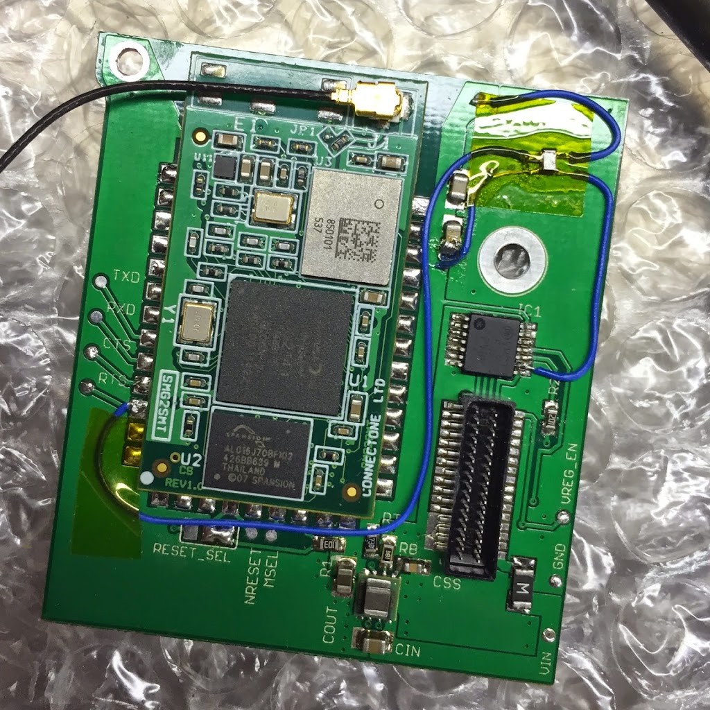
I soldered leads to a 1-gate logic inverter.  This wasn’t easy because the part is so small.  Then connect it to 3.3v, GND, and the RTS line coming out of the WiReach.  Then I cut the RTS trace on the bottom of the board.  I connected the output of the inverter to the input of the line driver IC.

Some Kapton tape holds it all in place.   It is a really terrible hack, but it works.  Hardware flow control works as expected, now.

I’m going to design a version 1.1 of the board that includes the inverter.  Also I can remove the extra GPIO/Reset stuff since the “power good/reset” circuit works.

WiFi Board For Newton: A Success?

I’m going to call this one a success.

There is an error in the hardware flow control circuit, but that’s due to an error in the N2 Platform documentation.  I’ll take responsibility because I should have more thoroughly prototyped (which I thought I had, but oh well)  I’m still planning on hacking an inverter onto the board to fix the issue.

Even so. I’m chalking this one up as a success.

A few last details:

The Antenna

I found a really small antenna.  I think its really for bluetooth devices, but it seems to work fine.  It is so small, I was able to tuck it in a small gap between the power connector and the interconnect port.

WiReach Configuration

You need to send a few specific commands to configure the WiReach module.  The most important is AT+iWANS=1  which tells the WiReach that the WiFi network is the WAN subnet.  Also you need to configure a username and password (which matches the PPP configuration on the Newton.)  AT+iRAU and AT+RAP are the commands you use to set the username and password.  And of course you’ll need to connect to your network using:

AT+iWLSI=My_WiFi
AT+iWST0=4
AT+iWPP0=<WPA2 passphrase>

I use PT-100 to configure the module.  Then a Serial Internet configuration with a script.  The script is simple.  First, it pauses for a few seconds to give the module time to power on.  Second, it sends the at+iSPPP:0 command to start the PPP server.  Finally, it waits for the OK.

How Does it Work?

My goals when I started this were:

  • The case had to close and everything had to be fully internal.  
  • Find an antenna and antenna placement that would work without modifying the case or the shielding.
  • Enough range to reach my router from my couch…
  • Connecting my Newton to a WPA2 network.

In all, despite the flow control thing, I’m pretty happy with the end result.  The project meets my requirements.

I’m trying to decide if I want to do a v1.1 board with corrected flow control signals.

Subsystem Power Configuration for Fun and Profit

Up till now, I have been following Ekhart’s template for enabling the serial signals: directly calling the ROM functions to toggle SerPortSel.  The only issue with this approach is that the OS also toggles these signals when a port is opened.  This means you have to configure the signals after the serial port is opened.

Wouldn’t it be great if you could tell NewtonOS that you wanted SerPortSel to be “set to internal” when you open Serial0 or Serial3?

The trick is the functions TVotagerPlatform::SetSubsystemPower() and its twin TVotagerPlatform::GetSubsystemPower().  These functions involve a bitmask that tells the Newton which power rails a subsystem requires.  It is a 8-bit mask but is set/returned as a ULong.  By looking at the disassembly of TVoyagerPlatform::PowerOnSubsystem(), I have found the following flags:

#define kNeedsPowerOnSrc5v     0x01
#define kNeedsPowerOnSrc12v   0x02
#define kNeedsPowerOnIC5v     0x08
#define kNeedsPowerOnDMA       0x10
#define kSetPortSelectExternal 0x20

The constant names are my own invention.  The key one is kSetPortSelectExternal.  When this bit is set, the NewtonOS conigures the SerPortSel LOW, indicating an external device connected to the interconnect port.  When this bit is clear, it configures the SerPortSel HIGH, indicating that the internal serial slot will use the port.

These functions need an index or ID of the subsystem involved.  Again, looking at the disassembly, you find the relevant index.  There may be more, but the ones involving the serial port are:

#define kSerial0SubsystemIndex 1
#define kSerial3SubsystemIndex 3

Again, the constant names are invented.  So some simple pseudocode to tell NewtonOS “when you open ‘mdem’ set SerPortSel3 to HIGH” might be:

theVotagerPlatform->GetSubsystemPower(3, &flag);
flag &= ~0x20; // clear the bit, setting internal
theVotagerPlatform->SetSubsystemPower(3, flag);

When the serial port is opened in software, the NewtonOS reads the bitmask and enables the proper voltage supplies and sets the SerPortSel apporopriately.  When the port is closed, the GPIO line is returned to its default state.  Note for Serial0, the default state is “internal” (HIGH) until you open the port, as this disables the LTC1323 (used on the external port), probably to save power.

These settings are reset on reboot, which I think is probably for the best.  You could always have a Pacakge that sets the flags on boot.

Currently, this is what I consider the “right way” or at least the “best known way” to use the serial port select signal for the internal slot.  It is much better than manually toggling the signal with the SerialPortXLineDriverConfig functions.

I dislike hardware flow control

I can’t ever seem to get the flow control lines right.   The current prototype only works with flow control disabled.

The N2 Platform docs says that the Serial3 signals are”ModemNotCTS” and “ModemNotRTS”.  The WiReach docs also use inverted signals “nCTS” and “nRTS”.  So I connected them up to each other thinking that they’re all using the same signaling logic.

But I was wrong, and I think the n2 docs are too.  It seems that the Newton’s CTS line is not inverted.  This can be verified with a  loopback.  When RX-TX are connected and RTS-CTS are connected, you will not get an echo when hardware flow control is enabled.

Similarly, if you connect CTS to GND, you won’t get an echo.  If you connect CTS to 3v, you get the echo.

So this tells me that CTS is not inverted.  Per this site:

RTS and CTS are normally held high (TTL 1).  When high, no request (RTS) has been made, and no permission (CTS) has been granted.  When the PC is ready to send data, it brings TTL RTS low.  The MCU sees this.  When the MCU is ready to receive data, it brings TTL CTS low.  The PC sends data as long as TTL CTS is low, and stops when the MCU takes TTL CTS high.

The opposite seems to be happening no the Serial3 signal.

So what next? Well the board works fine without hardware flow control… but I’m going to try and “dead bug” a 1 gate inverter onto the board on the RTS line coming from the WiReach.  It won’t be pretty, but it should work.

Serial Channel 2

The Newton’s internal serial slot exposes 3 serial channels.   Serial 1 and Serial 3 are the most interesting, as they have a full set of signals and are selectable by the selection signals.

I was searching for a way to control SerPortSel3 within software.  When you open the serial port on the Newton, it sets SerPortSel3 LOW.  I had hoped there was a parameter you could pass to the endpoint that would keep SerPortSel3 high.  (See earlier posts)
I was searching the DDK headers and I found this (HALOptions.h)
#define kHWLocExternalSerial ‘extr’
#define kHWLocBuiltInIR ‘infr’
#define kHWLocBuiltInModem ‘mdem’
#define kHWLocPCMCIASlot1 ‘slt1’
#define kHWLocPCMCIASlot2 ‘slt2’
#define kHWLocPCMCIAAnySlot ‘slot’
#define kHWLocBuiltInExtra ‘tblt’
kHWLocBuiltInExtra seemed promising.  I haven’t seen it mentioned in any of the other docs.  So I whipped up a little package to enable it as a valid modem location:
InstallScript := func(partFrame,removeFrame)
   begin
AddArraySlot(GetGlobals().ModemLocations, {title: “Modem”, id:”mdem”});
AddArraySlot(GetGlobals().ModemLocations, {title: “Extra”, id:”tblt”});
   end;
I had hoped that ‘tblt’ would open Serial3 and set SerPortSel high.  This is not the case.  It turns out that kHWLocBuiltInExtra is actually Serial Channel 2.
The n2 platform documents say that SerialChannel2 is a “low speed channel for printer support”.  I’ve also seen references that Serial2 is for keyboard.  Since Serial2 is not exposed on the external port, I don’t think that it is used for the keyboard.
In all, kHWLocBuiltInExtra is one more piece of the internal serial slot puzzle.