Upgrading the X-axis wiring harness to a “continuous flex” rated cable.
WARNING#
READ ALL OF THIS BEFORE PROCEEDING#
- This upgrade is not trivial and requires some thought and skill.
- You should understand what you are doing. The information here is not intended as a set of step by step instructions. You should engineer your own solution, which may wind up being better than mine.
- I think its a good long-term fix, but I can’t guarantee that it won’t fail in spectacular fashion at some later date. Nor am I claiming that my installation is either correct or ideal. This is just what I happened to come up with. Again, I’d invite people to take the cable and connectors and come up with their own solution, and maybe one better than my own.
- Proceed at your own risk. You’ve been warned. If you break your bot, burn your house down, or injure yourself or others, I take no responsibility.
This information is provided by the author “as is” and any express or implied warranties, including, but not limited to, the implied warranties of merchantability and fitness for a particular purpose are disclaimed. In no event shall the author be liable for any direct, indirect, incidental, special, exemplary, or consequential damages (including, but not limited to, procurement of substitute goods or services; loss of use, data, or profits; or business interruption) however caused and on any theory of liability, whether in contract, strict liability, or tort (including negligence or otherwise) arising in any way out of the use of this software, even if advised of the possibility of such damage.
Background#
The X-axis cable on the Replicator 2 and 2X is a known failure point. It is the only cable on the bot (with the exception of the extruder umbilical) that is in constant motion. MBI used a standard PCV jacketed IDC (Insulation Displacement Connector) ribbon cable. These cabes are not rated for “continuous motion”. Over time repeated flex in this cable causes an X-axis failure.
One option is to stress relieve the cable in a way that limits its motion. The Replicator 2/2X X-Harness Strain Relief thing was intended to help prevent the cable from flexing repeatedly. Some report that it helps, but the cable still eventually fails.
The proper cable for this application is one designed for motion applications and is rated for “continuous flex”. One such cable is the Cicoil Hi-Flex Cable This cabe is expensive and has a minimum special order fo 50 feet from Digikey. I ordered up some and some connectors and got to work.
Printed Parts#
I modified my “Replicator 2/2X X-Harness Strain Relief” thing to work with the new cable. Also you need a little clip to replace the zip tie and tie clip that holds the harness in the top rail.
Download the STL here: ExtensionPartsV2.stl (Oops, I plated V1 wrong such that both parts weren’t against the build plate. Sorry for anyone who tried to print V1)
Working With Cicoil#
Working with Cicoil Hi-Flex Unshielded Cable takes some thought and care. The cable is not “zipable” which means you can’t simply tear the conductors apart like you would with standard IDC ribbon cable. To separate out the conductors, you need to carefully cut them apart using an exacto knife. Unfortunately, there isn’t much room for error, and if you slip with the knife, you can find yourself exposing conductors unintentionally. See the diagram below for an attempt at showing the challenges involved.
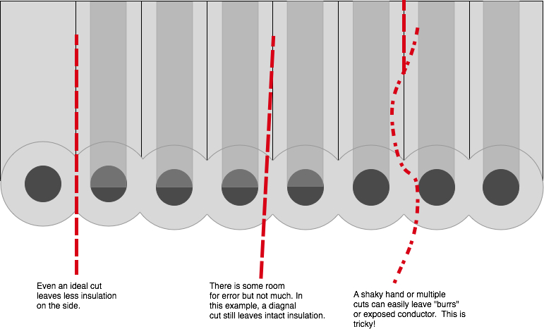
This takes a patient and steady hand. I did mine under the magnifying glass, and still wasn’t confident in the insulation after my slicing job. Hence I used a lot of heat shrink to make sure that there were no potential areas where a short could occur. The entire cable is .5″ across, so this is close-quarters cutting.
Working with crimp pins#
You could just splice in this cable directly into the exiting harness, which might be easier, but involves cutting the existing harness. Crimping the pins is difficult, even with the right crimp tool, and I’m guessing no one has the right crimp tool. Also, the insulation is pretty thick on this cable, and you can’t actually crimp the pins such that the “strain relief” portion of the crimp bites into the insulation. My process was as follows:
- Tin the wire with a THIN coat of solder
- Tin the inside of the crimp connector (only the crimp area, not near the active pin area) with a THIN coat of solder
- Tack the wire to the connector with the iron
- Crimp the pin. I had a crimp tool that wasn’t the right one, but did somewhat of a passible job. You could do this carefully with needle nose pliers and a steady hand
- Heat the completed assembly with a touch of solder to reflow the solder and get a nice finished solder job to the now-crimped pin. Important not to leave a glob of solder, you can’t change the outer diameter of the pin crimp area otherwise it won’t press into the housing.
- Use a punch tool to carefully push the pins into the housing.
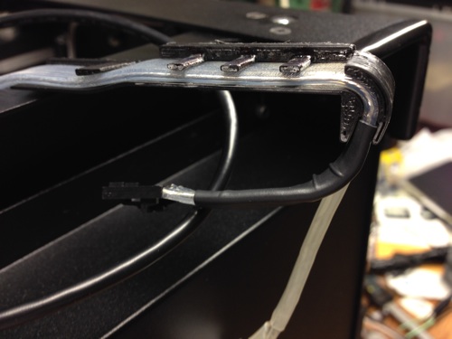
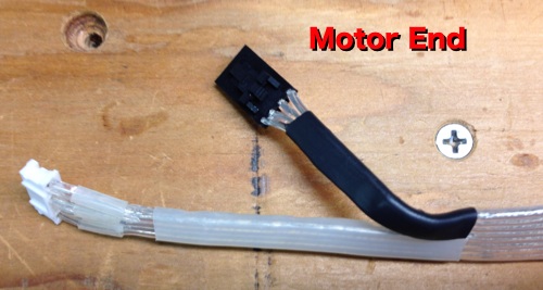
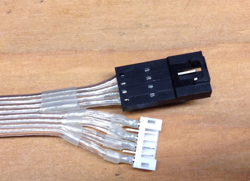
As far as I could find, there was no male wire-end housing connector for the motor. Instead, use a header connector meant for thru-hole PCB use. You need to solder the wires to this header, but with heat shrink tubing staged on the wire leads so that you can protect the exposed solder connectors after you’ve completed the solder job. See the pictures for the completed assembly.
The motor requires only 4 wires, even though the connector has 6 pins. Pins 2 and 5 are unconnected. The motor pins come on “cut tape”, which means you need to carefully bend the crimp pin back and forth until it comes off the ribbon before you can use it.
Connectors#
Here are the parts I used
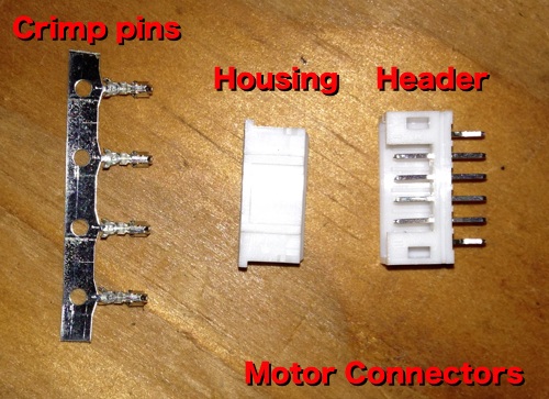
** Motor: **
– Male Connector MOLEX 89400-0620 (This is actually thru-hole PCB component, they don’t seem to make a wire-end connector, so you have to solder/heat shrink similar to how Makerbot does the fan connectors on the extruder.)
– Female Connector MOLEX 87369-0600
– Female Pins MOLEX 50212-8000
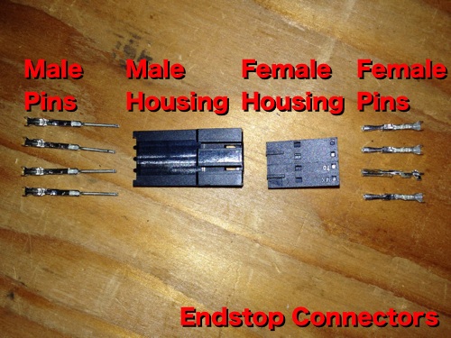
** Endstops **
– Female Connector MOLEX 50-57-9404
– Male Connector MOLEX 70107-0003
– Female Pins MOLEX 16-02-0096
– Male Pins MOLEX 16-02-0114
Assembly#
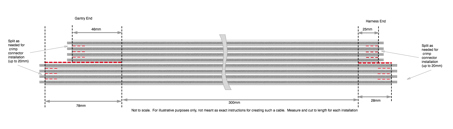
Its important to make sure you’re building an “extension cable” not a “crossover cable”, so you have to pay particular attention to the orientations of the connectors otherwise you could be having a bad day, doing damage to your mightyboard, endstop, motors, etc.
Start by splitting out the conductors for the gantry end of the cable, and route and fit the cable until you have a cable routing that you like. I wound up shortening the the endstop cable just a little so that the cable routed a little better.
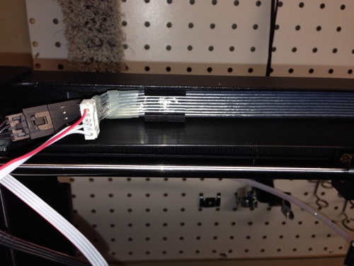
Here is a diagram of how my finished cabe turned out. This is NOT meant to be an instruction on how to replicate my cable exactly, just to show you how mine turned out. I think there are improvements to the length and routing of my cable, and I recommend that you figure out the lengths that work best for you rather than just copying this.
After assembly, make sure to use a multimeter to check for shorts and to verify that you have a straight-through cable. Also, I used my meter probe to run along any exposed slices in the Cicoil to look for breaks in the insulation. This isn’t really a perfect process, so I’m not sure if it would really detect any problems. I used a lot of heat shrink, so there weren’t many sections of insulation that I had cut that were exposed anyway.
Important warnings#
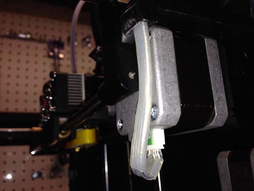
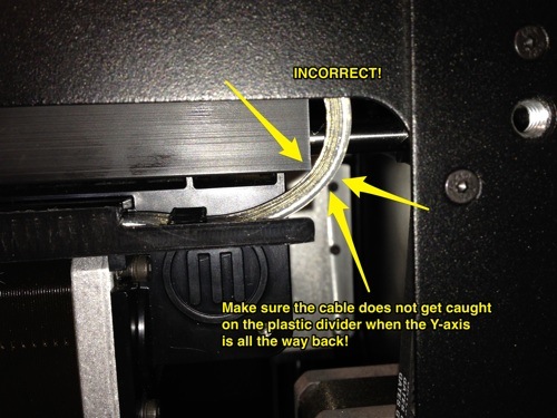
When the cable is installed, it is important that you make sure that the loop of cable does not (and cannot) get caught on the corner of the plastic divider between the gantry and the wire race channel. I’m not sure what would happen, but I’m sure it would be bad. See this picture:
Buy#
Sorry, I’ve sold out all of the kits. Thanks to everyone who helped subsidize the cost of a rather long spool of Cicoil and making it more affordable.